CANEO series5x + Allen-Bradley — Add-On Instruction Guide
This guide walks through integrating a CANEO series5x Duo-Touch Display with an Allen-Bradley ControlLogix or CompactLogix controller in Studio 5000 Logix Designer. By the end you'll be reading touch zones from the button and writing text, numbers, text color, and LED scenes to it from ladder logic — all through a single CAPTRON Add-On Instruction (AOI) that hides the byte-level plumbing.
Most IO-Link masters on EtherNet/IP hand the controller its process data as one flat SINT array covering every port on the block. Several CANEO series5x fields — the active scenes, the displayed number, and the text string — are larger than one byte, and some masters also swap the byte order. The AOI takes care of both: you point it at the master's raw arrays and tell it where your port starts, and it gives you back two clean, named structures to read and write.
Prerequisites
Before starting, make sure:
- Studio 5000 Logix Designer is installed and you have a project open for your controller. This example uses a 5069-L306ER CompactLogix on firmware v38.
- An IO-Link master is configured under I/O Configuration and its input and output data are visible as controller tags. This example uses a MURR IMPACT67 Pro E DIO8 IOL8 M12L 5P (54631).
- The CANEO series5x Duo-Touch Display is wired to an IO-Link port on the master (this example uses port 0).
- You have downloaded
CANEOseries5x_V34_AOI.zipand unzipped it to get the AOI fileCANEOseries5x_V34_AOI.L5X(see Download at the end of this guide). - You have the CANEO series5x IO-Link process data layout handy for the meaning of each value: series5x IO-Link Process Data.
1. Import the Add-On Instruction
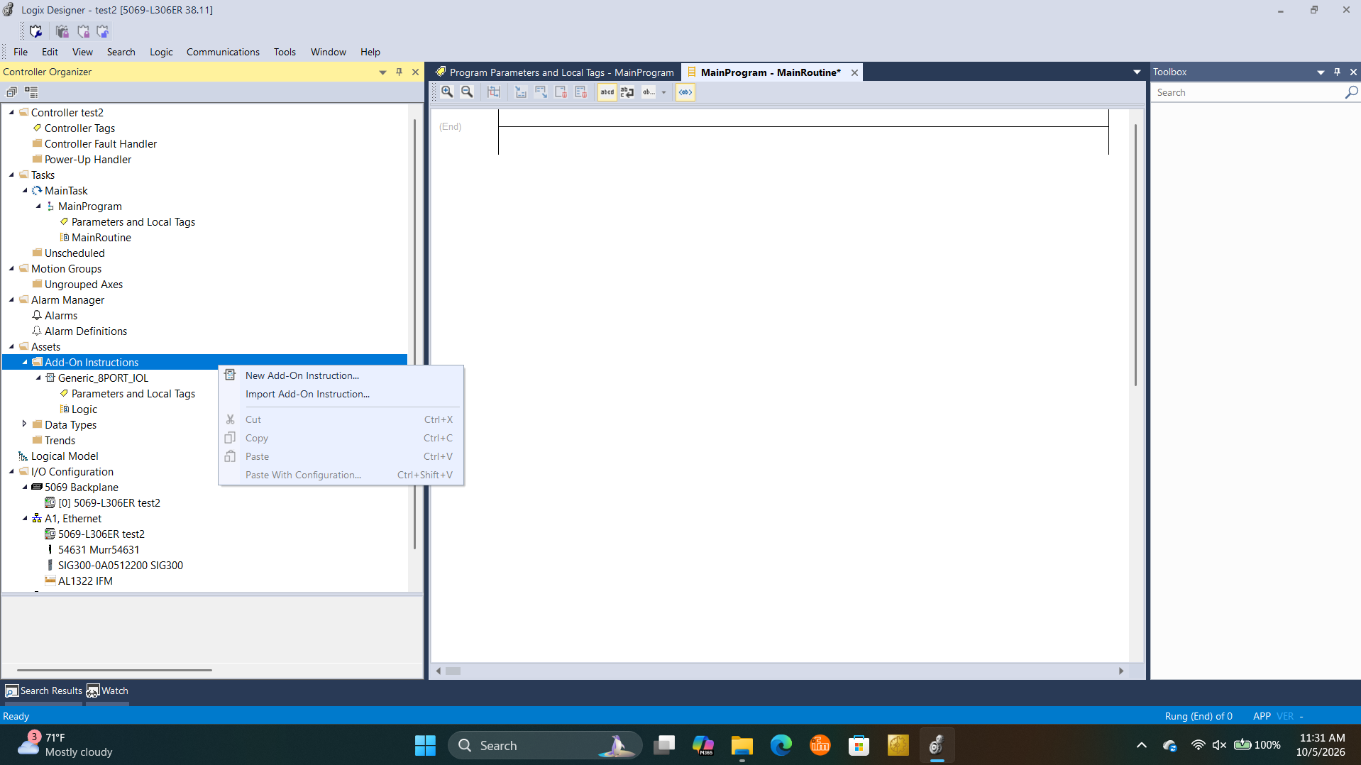
In the Controller Organizer, expand Assets, then right-click Add-On Instructions and choose Import Add-On Instruction….
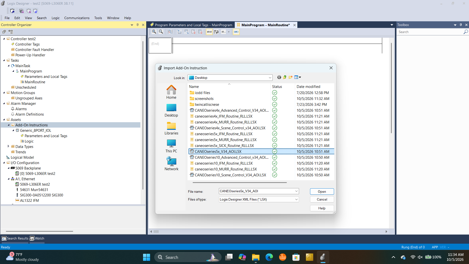
Browse to the downloaded file, select CANEOseries5x_V34_AOI.L5X, and click Open. Confirm the import dialog that follows.
After the import, AOI_CANEOseries5x_V34 appears under Add-On Instructions, and two user-defined data types (UDTs) appear under Data Types → User-Defined:
CaneoSeries5x_PDIN— the process data coming from the display (touch zones).CaneoSeries5x_PDOUT— the process data going to the display (text, number, color, scenes).
2. AOI parameters
Open the AOI definition and switch to the Parameters tab to see what the instruction expects.
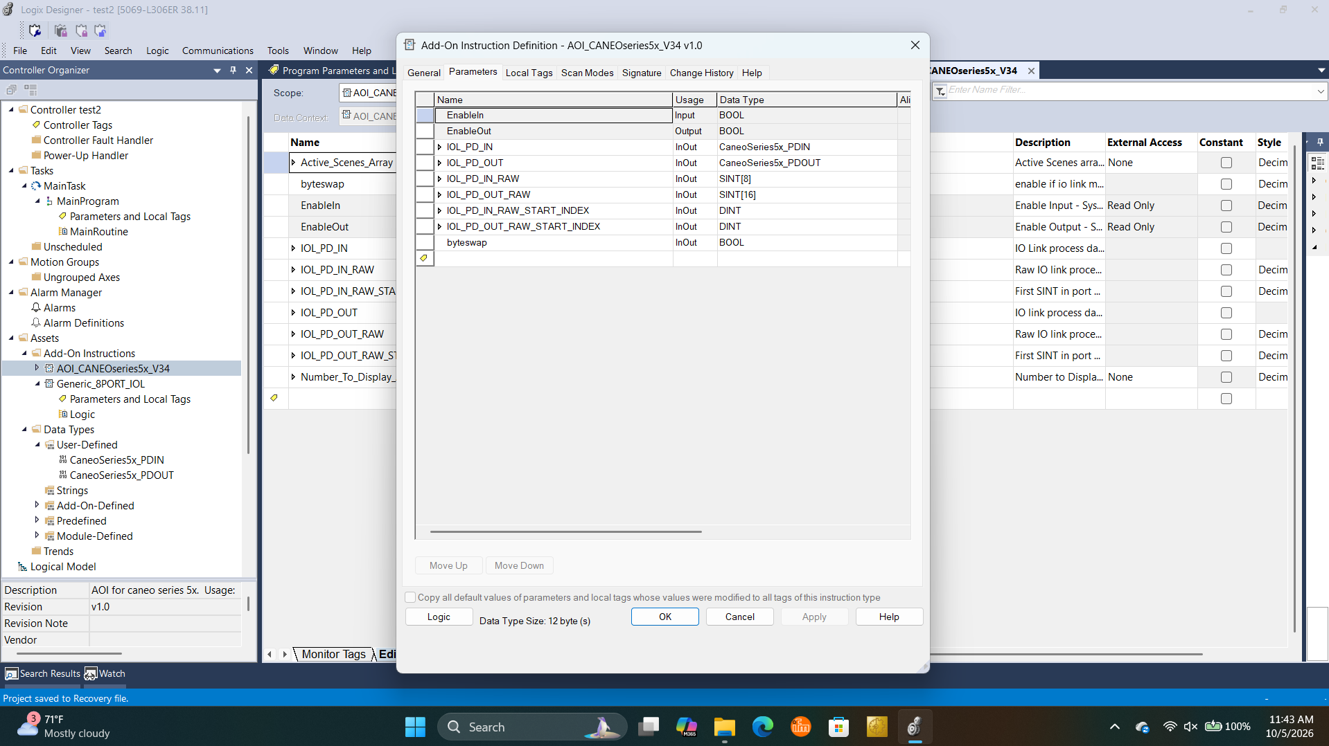
| Parameter | Data type | Description |
|---|---|---|
IOL_PD_IN | CaneoSeries5x_PDIN | Structure the AOI fills with the CANEO series5x input process data. Read the touch zones from here. See Reading the touch zones. |
IOL_PD_OUT | CaneoSeries5x_PDOUT | Structure you write to. The AOI packs it into the output process data. See Writing to the display. |
IOL_PD_IN_RAW | SINT[8] | The raw IO-Link input process data array from the IO-Link master (as defined by the master's EDS file). |
IOL_PD_OUT_RAW | SINT[16] | The raw IO-Link output process data array from the IO-Link master (as defined by the master's EDS file). |
IOL_PD_IN_RAW_START_INDEX | DINT | Index of the first input byte of the port the CANEO series5x is connected to. Consult your IO-Link master's manual for the byte layout. |
IOL_PD_OUT_RAW_START_INDEX | DINT | Index of the first output byte of the port the CANEO series5x is connected to. Consult your IO-Link master's manual for the byte layout. |
byteswap | BOOL | Set to 1 if your IO-Link master swaps the byte order of the process data. Default is 0 (no swap). |
Do I need byte swapping? IO-Link masters don't all format process data the same way. Some present each 16-bit word with its two bytes swapped. Masters from Turck, IFM, and Comtrol commonly do this. If text appears with pairs of characters swapped (e.g.
BADCEinstead ofABCDE), or touch zones show up on the wrong zone, setbyteswapto1.
3. Add the AOI to your routine
Open your routine (here MainProgram → MainRoutine) and add AOI_CANEOseries5x_V34 to a rung — you'll find it in the Toolbox under Add-On. Every operand starts as a question mark.
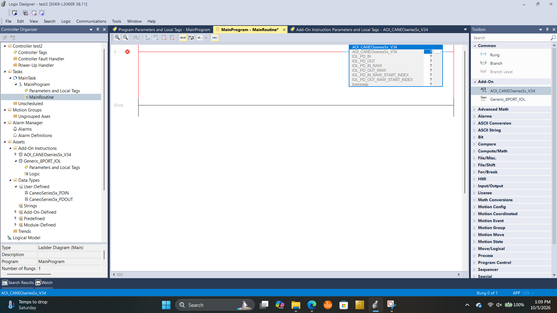
Fill in the operands one by one. For the tags that don't exist yet, right-click the question mark and choose New Tag:
- AOI instance — create a new tag of type
AOI_CANEOseries5x_V34(e.g.AOI_port0_MURR). Use one instance per display. IOL_PD_IN— create a new tag of typeCaneoSeries5x_PDIN(e.g.CD50_PDIN_port0).IOL_PD_OUT— create a new tag of typeCaneoSeries5x_PDOUT(e.g.CD50_PDOUT_port0).IOL_PD_IN_RAW/IOL_PD_OUT_RAW— select the IO-Link master's input and output data arrays from the Controller Tags.IOL_PD_IN_RAW_START_INDEX/IOL_PD_OUT_RAW_START_INDEX— enter the index of the first input and output byte of the port the CANEO series5x is connected to. These values are specific to your IO-Link master. If your master (or the master manufacturer's own AOI) already gives you a separate array per port, the start index is most likely0.byteswap—0or1, depending on your master (see above).
Example: MURR IMPACT67 (54631), port 0
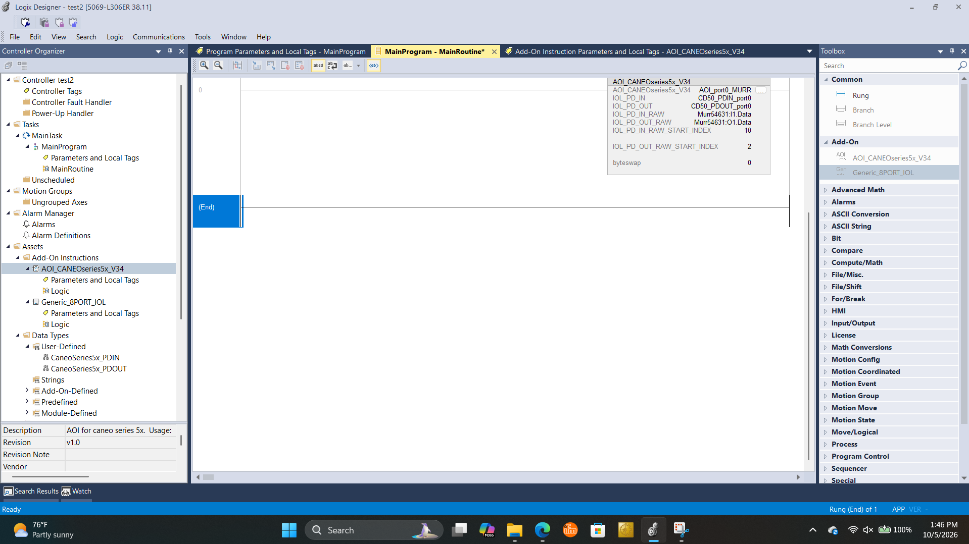
| Operand | Value | Why |
|---|---|---|
| AOI instance | AOI_port0_MURR | Named after the port and the master it serves. |
IOL_PD_IN | CD50_PDIN_port0 | Named after the part number (CD50), the type of process data, and the port. |
IOL_PD_OUT | CD50_PDOUT_port0 | Same naming scheme for the output side. |
IOL_PD_IN_RAW | Murr54631:I1.Data | The MURR block's complete input data array, stored under Controller Tags. |
IOL_PD_OUT_RAW | Murr54631:O1.Data | The MURR block's complete output data array. |
IOL_PD_IN_RAW_START_INDEX | 10 | First input byte of port 0 in the MURR input array. |
IOL_PD_OUT_RAW_START_INDEX | 2 | First output byte of port 0 in the MURR output array. |
byteswap | 0 | The MURR block does not swap bytes. |
In this example the entire MURR data array is passed in, and the start indexes tell the AOI where port 0's data begins inside it. To connect a display on another port, add a second AOI instance with its own PDIN/PDOUT tags and that port's start indexes.
4. IOL_PD_IN — reading the touch zones
CaneoSeries5x_PDIN holds one BOOL per touch zone. Each one goes high when its zone is actuated, according to the Touch Input parameters configured in the IODD.
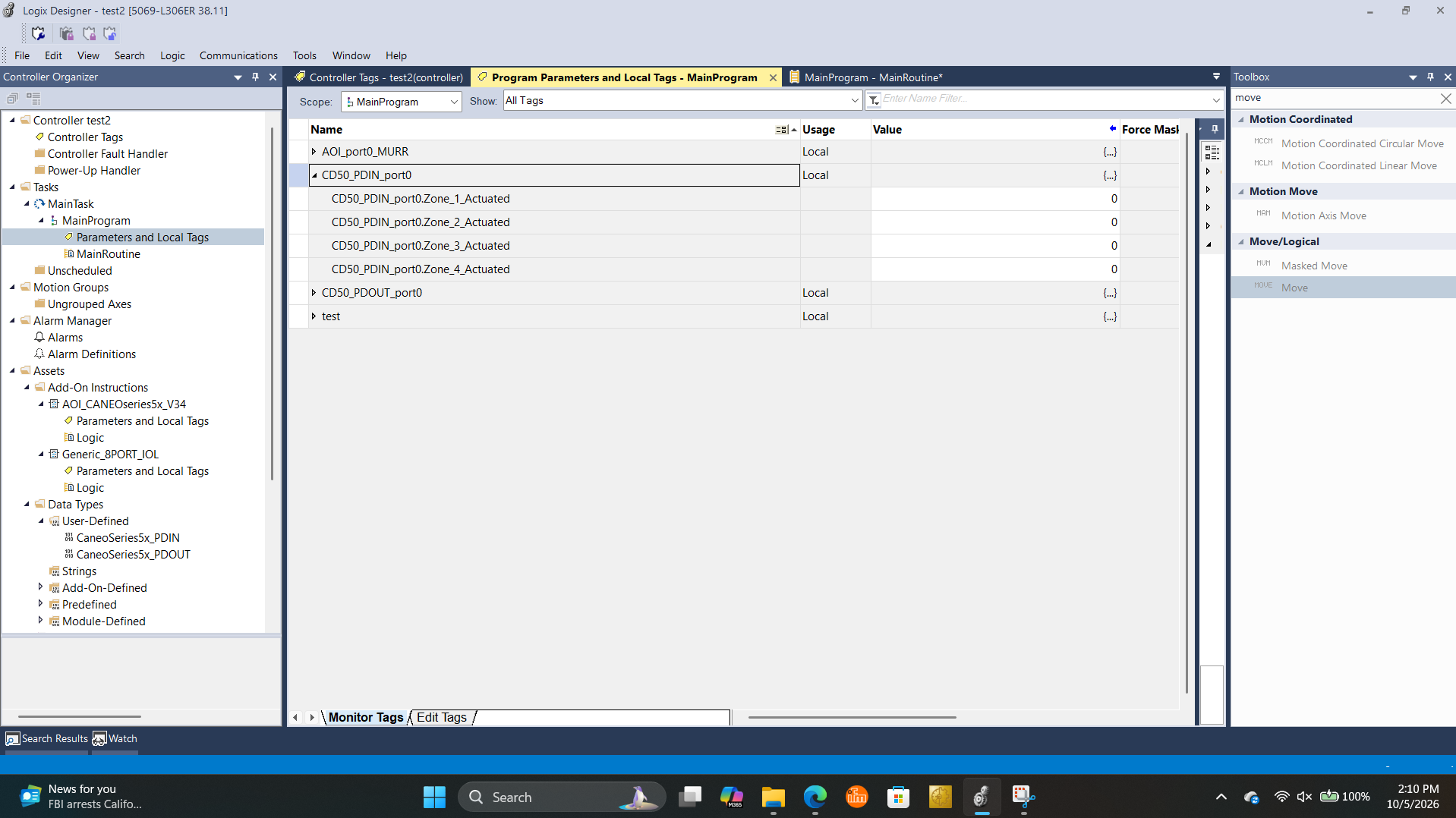
| Member | Data type | Description |
|---|---|---|
Zone_1_Actuated | BOOL | Touch zone 1 is actuated |
Zone_2_Actuated | BOOL | Touch zone 2 is actuated |
Zone_3_Actuated | BOOL | Touch zone 3 is actuated |
Zone_4_Actuated | BOOL | Touch zone 4 is actuated |
For more on how the touch zones are laid out and configured, see series5x Touch Zones.
5. IOL_PD_OUT — writing to the display
CaneoSeries5x_PDOUT holds everything you send to the display. Write to these members from your logic; the AOI copies them into the correct output bytes on every scan.
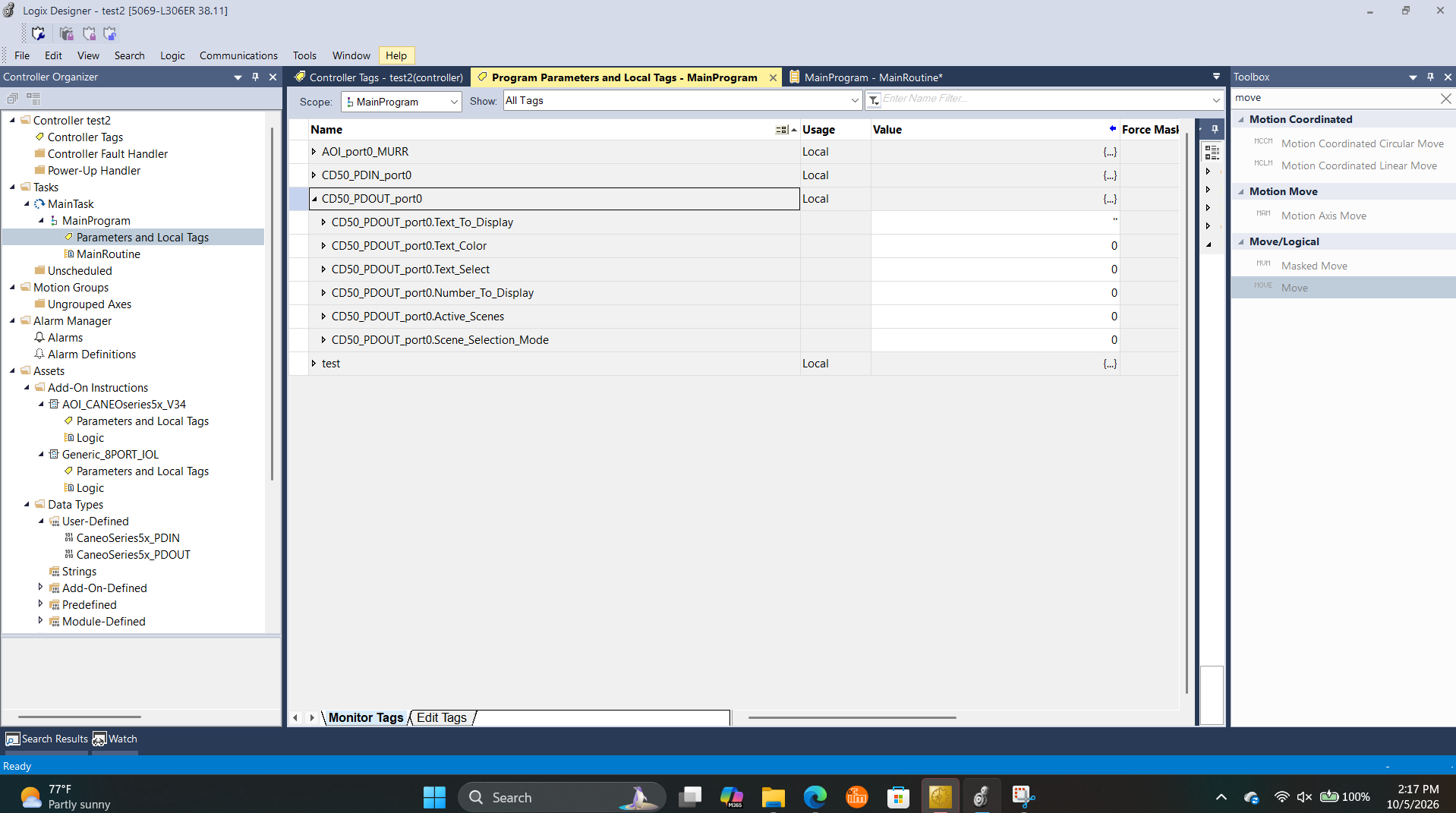
| Member | Data type | Description |
|---|---|---|
Text_To_Display | STRING | Text shown on the display — up to 5 characters. |
Text_Color | SINT | Color of the text, selected by number (e.g. 1 = Red, 2 = Green, 3 = Blue). |
Text_Select | SINT | What the display shows: 0 = text from the active scene (IODD), 1 = the number from Number_To_Display, 2 = the text from Text_To_Display. |
Number_To_Display | ULINT | Number shown on the display — up to 5 digits. |
Active_Scenes | UINT | Bitmask of the active scenes, up to 16 scenes. Bit 0 = scene 1, bit 1 = scene 2, and so on — write 1 for scene 1, 2 for scene 2, 4 for scene 3, 8 for scene 4. |
Scene_Selection_Mode | SINT | 0 = Local Data (scenes are activated by the configured triggers in the IODD), 1 = Process Data (scenes follow the bits in Active_Scenes). |
Active_Scenesonly takes effect in Process Data mode. SetScene_Selection_Modeto1before you expect the display to follow the scenes you write.
For the full list of color codes and the details of each field, see series5x IO-Link Process Data.
6. Usage example
The ladder logic below switches scenes based on touch zone 1 and writes a text string to the button.
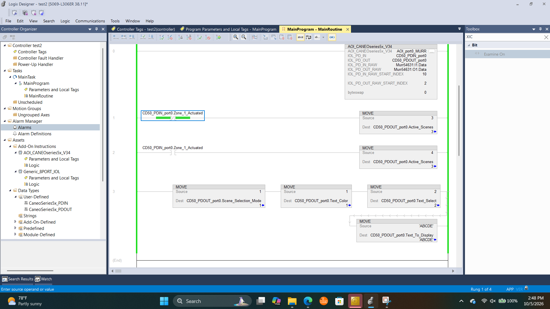
- Rung 0 — calls the AOI. It must be scanned on every cycle, so leave it unconditional.
- Rung 1 — while zone 1 is not actuated (
XIO),MOVE 3intoActive_Scenes— scenes 1 and 2 are active. - Rung 2 — while zone 1 is actuated (
XIC),MOVE 4intoActive_Scenes— scene 3 is active. - Rung 3 — sets
Scene_Selection_Modeto1(Process Data) so the display followsActive_Scenes,Text_Colorto1(Red),Text_Selectto2(show the text from process data), andText_To_Displayto'ABCDE'.
To show a number instead, set Text_Select to 1 and write the value to Number_To_Display.
7. Using integer arrays and an IO-Link master AOI (IFM AL1322)
Not every IO-Link master hands you its process data as a SINT array. The IFM AL1322 imports its data as an INT array. IFM also provides its own generic AOI, Generic_8PORT_IOL, which pulls a single port's process data out of the master's data and gives it to you as a separate array for that port.
The CAPTRON AOI expects SINT arrays for IOL_PD_IN_RAW and IOL_PD_OUT_RAW. So when your master works in INTs, you need to convert to SINT on the way into the CAPTRON AOI and back to INT on the way out. The CPS (Synchronous Copy File) instruction does this. It copies the raw bytes from one array into another, whatever the data type of each array.
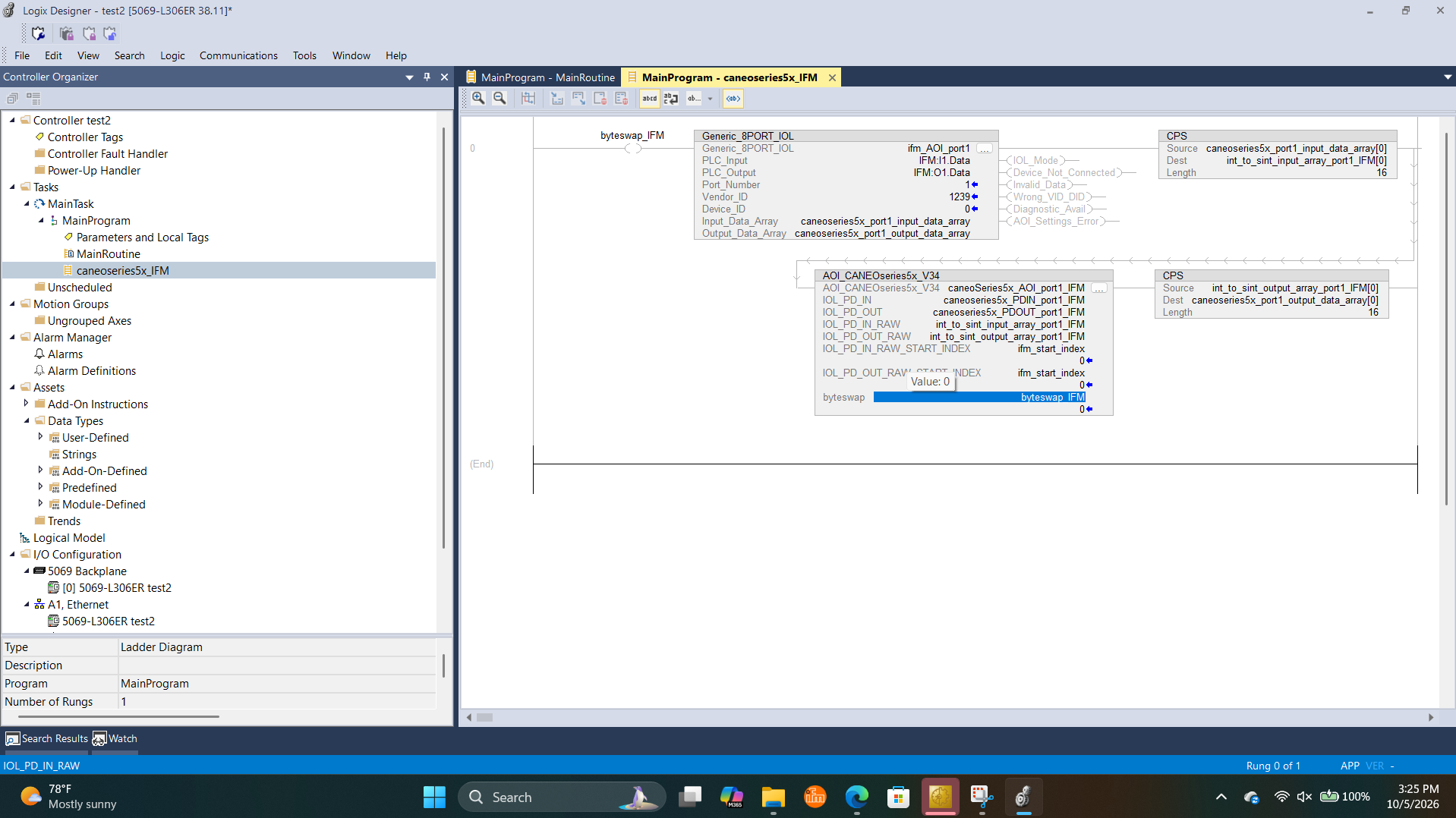
The rung runs in four stages:
Generic_8PORT_IOL(IFM's AOI) reads the master's data (IFM:I1.Data/IFM:O1.Data) for port 1. It places that port's process data incaneoseries5x_port1_input_data_arrayand takes the port's output data fromcaneoseries5x_port1_output_data_array. Both areINTarrays. For theVendor_IDandDevice_IDsettings and the status outputs, see IFM's documentation for the AOI.CPScopies theINTinput array into aSINTarray,int_to_sint_input_array_port1_IFM.AOI_CANEOseries5x_V34readsint_to_sint_input_array_port1_IFMasIOL_PD_IN_RAWand writes toint_to_sint_output_array_port1_IFMasIOL_PD_OUT_RAW, exactly as in step 3.CPScopies theSINToutput array back into theINTarraycaneoseries5x_port1_output_data_array. IFM's AOI then sends it to the master.
| CAPTRON AOI operand | Value | Why |
|---|---|---|
IOL_PD_IN | caneoseries5x_PDIN_port1_IFM | Touch zones for the display on port 1. |
IOL_PD_OUT | caneoseries5x_PDOUT_port1_IFM | Values you write to the display on port 1. |
IOL_PD_IN_RAW | int_to_sint_input_array_port1_IFM | The SINT copy of the port's input data. |
IOL_PD_OUT_RAW | int_to_sint_output_array_port1_IFM | The SINT array that is copied back to the port's output data. |
IOL_PD_IN_RAW_START_INDEX | ifm_start_index = 0 | IFM's AOI already returns only port 1's data, so it starts at index 0. |
IOL_PD_OUT_RAW_START_INDEX | ifm_start_index = 0 | Same as above, for the output side. |
byteswap | byteswap_IFM = 1 | The IFM master swaps the byte order, so byte swapping must be enabled. |
Keep the order: IFM AOI →
CPSin → CAPTRON AOI →CPSout. If the input copy runs after the CAPTRON AOI, the touch zones are one scan late. If the output copy runs before it, the display gets the values from the previous scan.
You can use the same pattern with any IO-Link master that delivers INT or DINT data, or that comes with its own port-parsing AOI. Convert to SINT with CPS, set the start index to the first byte of the port, and set byteswap to whatever that master needs.
Tested IO-Link masters
The AOI was created and tested with the following IO-Link masters:
- MURR IMPACT67 Pro E DIO8 IOL8 M12L 5P (54631)
- IFM AL1322 (byte swap enabled — see step 7)
- SICK SIG300
Other IO-Link masters on EtherNet/IP should work as long as you set the correct start indexes and byteswap value for that master.
Reference
- CANEO series5x IO-Link process data: https://docs.captron.com/trms/series5x/io-link-process-data
- CANEO series5x touch zones: https://docs.captron.com/trms/series5x/touch-zones
Download: Add-On Instruction
Download the CAPTRON Add-On Instruction used in this guide. It includes the CaneoSeries5x_PDIN and CaneoSeries5x_PDOUT data types. Unzip it and import the .L5X file as described in step 1.