CANEO series5x + Beckhoff EL6224 — IO-Link Integration Guide
This guide walks through integrating a CANEO series5x Duo-Touch Display with a Beckhoff EL6224 IO-Link terminal in TwinCAT 3. By the end you'll be reading touch inputs from the button and writing text, numbers, text color, and LED scenes to it from your PLC program — all through a single reusable function block (FB) that hides the byte-level plumbing.
The tricky part of an IO-Link integration on the EL6224 is that the terminal exposes process data as a flat array of individual bytes, while several of the CANEO series5x parameters (the active scene, the displayed number, and the text string) are larger than one byte. This guide shows how to stitch those multi-byte fields back together using TwinCAT DUTs and unions, so you can write to one clean variable instead of juggling raw bytes.
Prerequisites
Before starting, make sure:
- An EL6224 IO-Link terminal is installed in your EtherCAT node (e.g., behind an EK1200 coupler) and appears under I/O → Devices in TwinCAT.
- TwinCAT 3 is installed and can go online with the controller.
- The CANEO series5x Duo-Touch Display is wired to an IO-Link port on the EL6224 (this example uses port 1).
- You have the IODD file for your CANEO series5x variant (download it from CAPTRON).
- You have the CANEO series5x IO-Link process data layout handy — you'll reference it when mapping bytes: series5x IO-Link Process Data.
1. Wire the CANEO series5x into the EL6224
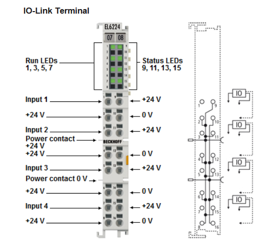
Wire the device leads into the EL6224 following the terminal's connection diagram. This example uses port 1.
For pinout, power-contact routing, and status-LED meanings, always refer to the official Beckhoff documentation: EL6224 manual (PDF).
2. Import the IODD and scan for the device
Open TwinCAT and go online with the controller.
- In the Solution Explorer, navigate to the EL6224 under I/O → Devices.
- Open the IO-Link tab.
- Click Import Devicedescription and select the IODD for your device. This example uses the CANEO series52 Duo-Touch Display.
- Click Scan devices. The CANEO series5x should appear on the port it's wired to (port 1 here).
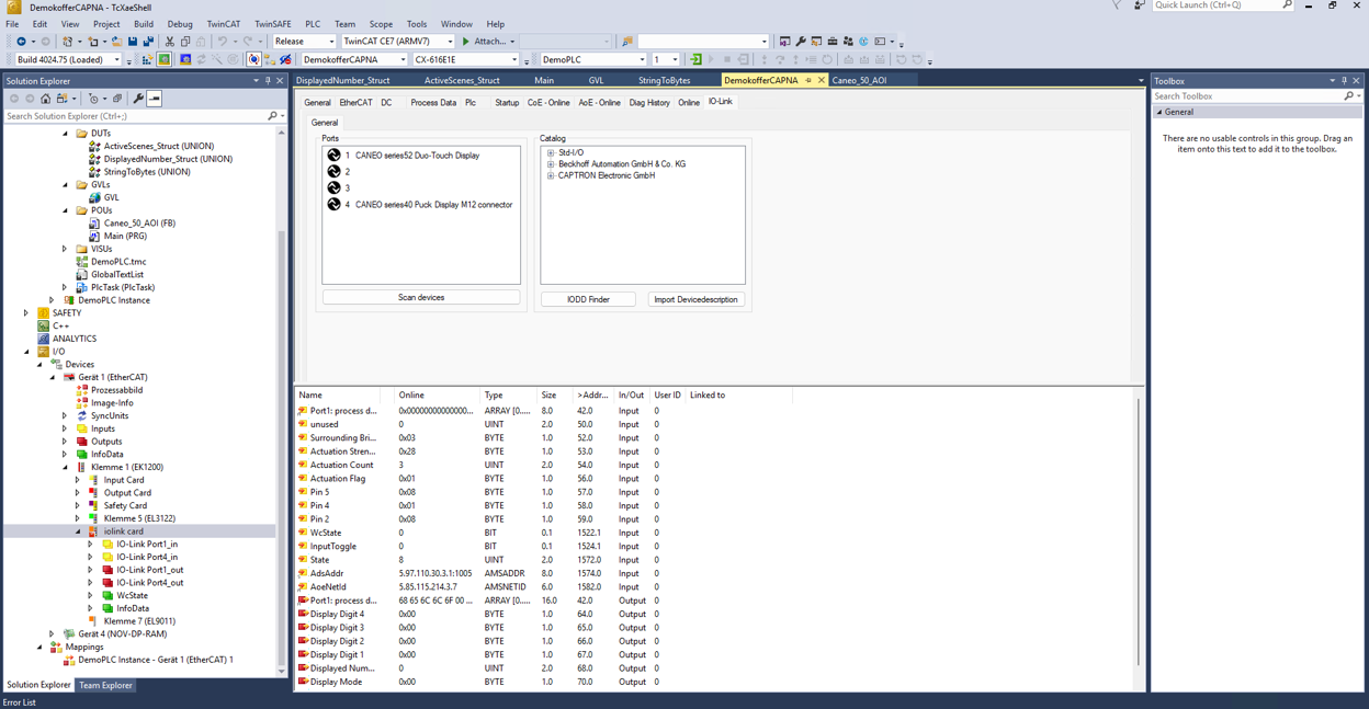
Why import the IODD first? The IODD tells TwinCAT the device's identity, parameters, and process-data structure. Without it, a scan will still detect something on the port, but you won't get the named parameters or the correct process-data layout.
3. Read the device parameters
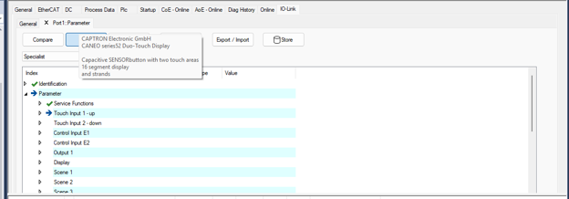
Double-click the port 1 device to open its parameter view, then read the IODD file so TwinCAT pulls the current parameter set from the device.
Under the Parameter tree you'll see the CANEO series5x configurable items — Service Functions, Touch Input 1 / 2, Control Inputs, Output, Display, Scene 1…n, and so on.
4. Enable the process data
Once the device is identified, switch back to General, then right-click and open Process Data.
On the Process Data page, tick Write to System Manager and Activate. You'll see the input and output process data laid out with their bit lengths and offsets.
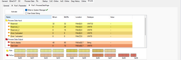
After activating, the input and output process data populate in the tag columns.

Expand the iolink card in the Solution Explorer and you'll see the raw process data broken out byte by byte — IO-Link Port1_in as Port1: process data[0…7] and IO-Link Port1_out as Port1: process data[0…15].
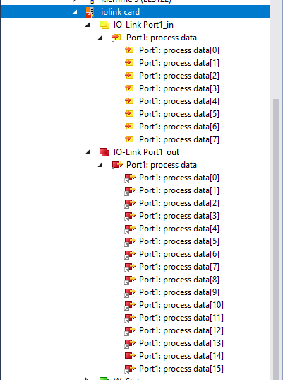
Now we need to link tags to the bytes that correspond to each parameter. Use the series5x IO-Link process data layout as your reference for which byte is which.
5. The multi-byte problem
The EL6224 exposes process data as individual bytes, but several CANEO series5x fields span more than one byte:
- Active Scenes — 2 bytes (
INT) - Number to Display — 4 bytes (
UDINT) - Text to Display — up to 6 bytes (a string)
You can't cleanly write a two- or four-byte value into single-byte process-data tags one at a time. To get around this, we combine the bytes into one variable using a DUT (Data Unit Type) built as a union.
A union overlays two views of the same memory: a friendly typed field (like an INT or a STRING) and a raw ARRAY … OF BYTE occupying the exact same bytes. Write the typed field, and TwinCAT automatically fills the byte array for you — no manual bit-shifting.
Create three DUTs.
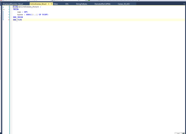
ActiveScenes_Struct
A 2-byte value (INT) overlaid with a 2-byte array.
TYPE ActiveScenes_Struct :
UNION
    num   : INT;
    bytes : ARRAY[0..1] OF USINT;
END_UNION
END_TYPE
DisplayedNumber_Struct
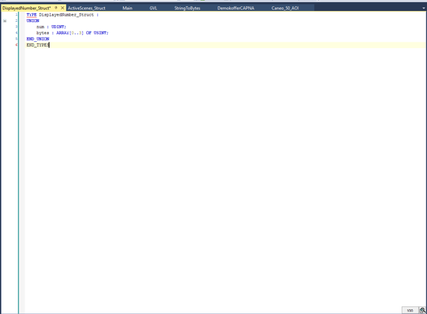
A 4-byte value (UDINT) overlaid with a 4-byte array.
TYPE DisplayedNumber_Struct :
UNION
    num   : UDINT;
    bytes : ARRAY[0..3] OF USINT;
END_UNION
END_TYPE
StringToBytes
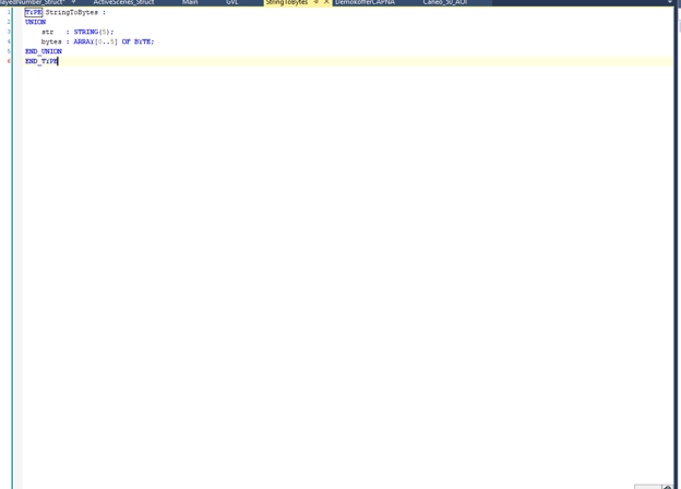
A 5-character string overlaid with a 6-byte array.
TYPE StringToBytes :
UNION
    str   : STRING(5);
    bytes : ARRAY[0..5] OF BYTE;
END_UNION
END_TYPE
Bundling it all: series5x_PDout and series5x_PDin
The three unions above solve the multi-byte problem, but on their own they leave you with a long, flat list of loose variables in the GVL — and that list repeats for every device you add. A second, cleaner step is to wrap one device's entire process-data image into two structs: one for everything you send to the display, one for everything you read from it.
These are ordinary STRUCT DUTs (not unions). They don't change how the data is packed — they just group it.
series5x_PDout — everything you write to the device
TYPE series5x_PDout :
STRUCT
    TextToDisplay : STRING(5);                          //value you write to
    stringToBytes : StringToBytes;                      //link raw data
    DisplayedNumber : UDINT;                            //value you write to
    displayedNumberStuct : DisplayedNumber_Struct;      //link raw data
    TextColor AT %Q* : USINT;
    TextSelect AT %Q*: USINT;
    ActiveScenes : INT;                                 // value you write to
    activeScenesSctruct : ActiveScenes_Struct;          //link raw data
    Mode AT %Q*: USINT;
END_STRUCT
END_TYPE
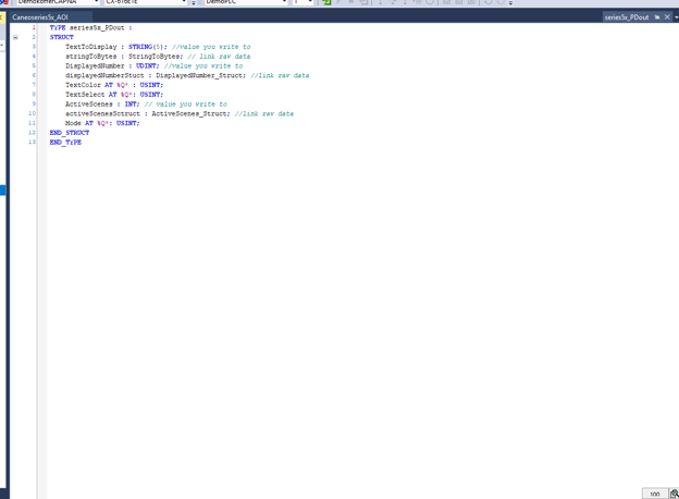
Read the member list as pairs. Each multi-byte field appears twice, and the two halves do different jobs:
| Member | Type | Role |
|---|---|---|
TextToDisplay | STRING(5) | The value you write in your program |
stringToBytes | StringToBytes | The union you link to raw process data |
DisplayedNumber | UDINT | The value you write |
displayedNumberStuct | DisplayedNumber_Struct | The union you link |
ActiveScenes | INT | The value you write |
activeScenesSctruct | ActiveScenes_Struct | The union you link |
TextColor | USINT AT %Q* | Single byte — write and link are the same variable |
TextSelect | USINT AT %Q* | Single byte — write and link are the same variable |
Mode | USINT AT %Q* | Single byte — write and link are the same variable |
The three single-byte members (TextColor, TextSelect, Mode) carry an AT %Q* address and need no partner, because a one-byte value maps straight onto one process-data byte. The three multi-byte fields can't do that, so each one keeps its plain typed member for you to write to and its union member for the mapping to attach to. The function block is what copies between the two halves of each pair.
series5x_PDin — everything you read from the device
TYPE series5x_PDin :
STRUCT
    Caneoseries5x_TouchZone1 AT %I* : USINT;
    Caneoseries5x_TouchZone2 AT %I* : USINT;
    Caneoseries5x_TouchZone3 AT %I* : USINT;
    Caneoseies5x_TouchZone4 AT %I* : USINT;
END_STRUCT
END_TYPE
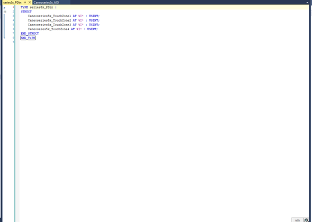
The input side is simpler. Every touch zone is a single byte, so there are no unions here at all — just four USINT members with AT %I* addresses, one per touch zone. This version covers four zones; trim or extend the list to match the number of zones your button actually has.
Why bundle at all? With these two DUTs you declare one instance of each per device instead of twenty-odd loose globals — for example
caneoSeries52_PDout_port1 : series5x_PDout;andcaneoSeries52_PDin_port1 : series5x_PDin;. Adding a second display becomes two more declarations rather than another twenty renamed variables, the mapping tree in TwinCAT groups every byte under its port's instance name, and you can pass a whole device's process data into a function block as a single argument.
6. Declare the GVL variables
Activate the configuration, then open the GVL (Global Variable List).
First declare the raw bytes for the three multi-byte fields. These are the variables the output process data links to, and they're called bytes because they hold raw data that the function block assembles from the unions. Give each one an AT %Q* address so it maps to output process data.
ActiveScenes_byte0_port1 AT %Q* : USINT;
ActiveScenes_byte1_port1 AT %Q* : USINT;

Number_byte0_port1 AT %Q* : USINT;
Number_byte1_port1 AT %Q* : USINT;
Number_byte2_port1 AT %Q* : USINT;
Number_byte3_port1 AT %Q* : USINT;

String_byte0_port1 AT %Q* : USINT;
String_byte1_port1 AT %Q* : USINT;
String_byte2_port1 AT %Q* : USINT;
String_byte3_port1 AT %Q* : USINT;
String_byte4_port1 AT %Q* : USINT;
String_byte5_port1 AT %Q* : USINT;

Only the three multi-byte fields need bytes like this. Mode, TextSelect, and TextColor are absent because a one-byte value maps straight onto one process-data byte and needs no union — they're handled in step 8. It's worth pasting the byte-to-process-data mapping from the next step into the GVL as a comment block while you're here; it's the one place that records which byte goes where.
7. Link the process data bytes
Go back to the IO-Link Port1_out process data in the Solution Explorer and link each GVL byte to the correct process-data byte position.
Open a byte's link dialog and pick the matching Port1 process data[n].
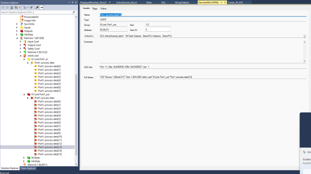
If the variables don't show up in the link dialog, make sure you activated the configuration after adding them to the GVL.
Use this mapping for the output process data:
| GVL variable | Output process data byte |
|---|---|
ActiveScenes_byte1_port1 | processdata[13] |
ActiveScenes_byte0_port1 | processdata[12] |
Number_byte3_port1 | processdata[11] |
Number_byte2_port1 | processdata[10] |
Number_byte1_port1 | processdata[9] |
Number_byte0_port1 | processdata[8] |
String_byte5_port1 | processdata[5] |
String_byte4_port1 | processdata[4] |
String_byte3_port1 | processdata[3] |
String_byte2_port1 | processdata[2] |
String_byte1_port1 | processdata[1] |
String_byte0_port1 | processdata[0] |
8. Declare the PDin and PDout objects
Back in the GVL, below the bytes, add the only other thing this device needs — one object of each DUT, named after the port they serve.
caneoSeries52_PDin_port1 : series5x_PDin;
caneoSeries52_PDout_port1: series5x_PDout;
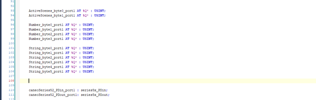
Everything else comes with them: the clean values you write, the unions the function block packs them through, the single-byte outputs, and the touch-zone inputs are all members of these two objects.
9. Build the Caneoseries5x_AOI function block
Now we pack the clean values into the raw output bytes. Create a Function Block called Caneoseries5x_AOI.
It needs no local variables — the unions already live inside caneoSeries52_PDout_port1, so leave the declaration part as TwinCAT creates it and write everything in the body.
The body does the same job in two moves per field: copy the clean value into the union's typed member, then copy the union's raw bytes out to the linked byte variables. TwinCAT fills the byte view for you — so writing one value (e.g. gvl.caneoSeries52_PDout_port1.ActiveScenes) ends up addressing multiple process-data bytes.
gvl.caneoSeries52_PDout_port1.activeScenesSctruct.num := gvl.caneoSeries52_PDout_port1.ActiveScenes;

gvl.ActiveScenes_byte0_port1 := gvl.caneoSeries52_PDout_port1.activeScenesSctruct.bytes[1];
gvl.ActiveScenes_byte1_port1 := gvl.caneoSeries52_PDout_port1.activeScenesSctruct.bytes[0];


//displayed number
gvl.caneoSeries52_PDout_port1.displayedNumberStuct.num := gvl.caneoSeries52_PDout_port1.DisplayedNumber;

gvl.Number_byte0_port1 := gvl.caneoSeries52_PDout_port1.displayedNumberStuct.bytes[3];
gvl.Number_byte1_port1 := gvl.caneoSeries52_PDout_port1.displayedNumberStuct.bytes[2];
gvl.Number_byte2_port1 := gvl.caneoSeries52_PDout_port1.displayedNumberStuct.bytes[1];
gvl.Number_byte3_port1 := gvl.caneoSeries52_PDout_port1.displayedNumberStuct.bytes[0];

gvl.caneoSeries52_PDout_port1.stringToBytes.str := gvl.caneoSeries52_PDout_port1.TextToDisplay;

gvl.String_byte0_port1 := gvl.caneoSeries52_PDout_port1.stringToBytes.bytes[0];
gvl.String_byte1_port1 := gvl.caneoSeries52_PDout_port1.stringToBytes.bytes[1];
gvl.String_byte2_port1 := gvl.caneoSeries52_PDout_port1.stringToBytes.bytes[2];
gvl.String_byte3_port1 := gvl.caneoSeries52_PDout_port1.stringToBytes.bytes[3];
gvl.String_byte4_port1 := gvl.caneoSeries52_PDout_port1.stringToBytes.bytes[4];
gvl.String_byte5_port1 := gvl.caneoSeries52_PDout_port1.stringToBytes.bytes[5];
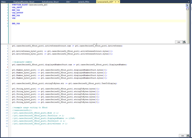
Watch the byte order — it differs per field, and all three cases matter.
ActiveScenes is byte-swapped:byte0takesbytes[1],byte1takesbytes[0].
Number is fully reversed:byte0takesbytes[3], down tobyte3takingbytes[0].
String is straight through:byte0takesbytes[0].
These orderings are what the CANEO series5x expects. Copy them exactly.
10. Call the function block from your program
In your main program, declare a local instance of the function block:
VAR
    caneoseries5x : Caneoseries5x_AOI;
END_VAR

11. Write to the display
Call the function block, then write to the members of caneoSeries52_PDout_port1. The function block packs them into the process data on the next scan.
caneoseries5x();

gvl.caneoSeries52_PDout_port1.Mode := 1;
gvl.caneoSeries52_PDout_port1.TextColor := 1;
gvl.caneoSeries52_PDout_port1.DisplayedNumber := 12345;
gvl.caneoSeries52_PDout_port1.TextSelect := 1;
gvl.caneoSeries52_PDout_port1.ActiveScenes := 1;
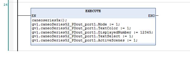
Notice that every write goes through the one instance — there are no per-field global names to remember, and pointing this block at a second display means changing the instance name and nothing else.
In this example we switched Mode to accept process data (Mode := 1), set a Text Select code, a Text Color, a Displayed Number of 12345, and an Active Scenes value. To display your own text instead of a built-in string, write to TextToDisplay as well — the function block copies it through stringToBytes for you:
gvl.caneoSeries52_PDout_port1.TextToDisplay := 'hello';
For the meaning of each value — the mode options, text-select codes, color codes, and the scene bitmask — reference the series5x IO-Link process data layout.
Reference
- CANEO series5x IO-Link process data: https://docs.captron.com/trms/series5x/io-link-process-data
- Beckhoff EL6224 manual (PDF): https://download.beckhoff.com/download/Document/io/ethercat-terminals/el6224_en.pdf
Download: example project
Download the ready-made TwinCAT objects used in this guide — the DUTs, the GVL, and the Caneoseries5x_AOI function block. Unzip it and add the objects to your TwinCAT project.